Radio Navigation Simulator
Introductory Note - Download Resources |
|---|
Supporting notes and charts, for the four exercise routes, and charts for the synthetic flight area, are available for download as PDF files. Single tap on the Settings Icon, and select the Download Resources option in the Settings dialogue. An internet connection is required for this action. The downloaded PDF file, can be redirected, using a forwarded email technique with the pdf attached or through iBooks or similar, to a destination computer, where the PDF file can be printed, and used alongside RNS as reference material, when flying any of the four exercises. |
Overview
Radio Navigation Simulator, referred to subsequently as RNS, is a 2D flight simulator, operating in a synthetic flight environment of navigation beacons and airfields.
RNS is equipped with flight instruments, flight controls, radio navigation instruments and receivers, enabling the user to practice radio navigation techniques and procedures, by flying the simulator in the synthetic flight environment, all depicted on a display chart. A management system is also incorporated, enabling full control of the facilities of RNS.
This Getting Started document provides an introduction to RNS, describing its basic facilities and operation.
Getting Started
| RNS ON-SCREEN DISPLAYS | |||||||||
The On-Screen display of RNS, comprises of:
|
|||||||||
| RNS - Typical Display | ||
|
||

| The User Interface Control | |||||||||||||||
The User interface operates using On Screen Finger Gestures to interact with the User manageable features and facilities of RNS. The User interfaces, for the iPad, iPhone and iPod, are all based on the same design, and each interface control point, has been carefully designed and located, to provide easy and direct access, when its management gesture is applied. The on screen Finger Gestures used to interface with the User manageable features and facilities of RNS, comprise of the following:
|
|||||||||||||||
Back to Index
| RNS Facilities | |||||||||||||||||||
The RNS is equipped with:
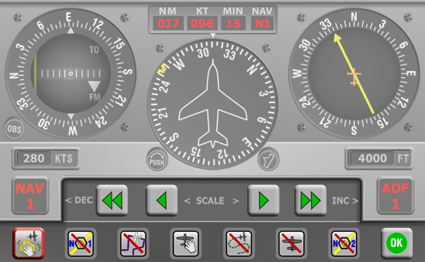
Flight Controls: Flight control is achieved by use of the five button control bar. The centre button acts as an indicator of aircraft attitude when a manoeuvre is being made. This button when single tapped, also terminates a manoeuvre, cancelling all of the control button selections.
The Top and Bottom Toolbars: The Top and Bottom tool bars contain Icon activated facilities and displays Other Embedded Features: There are in addition to the facilities visible on the normal display, other embedded features, these comprise of:
These are all activated by touching various Instrument Panel and Mapping Pane components of the RNS display. Each RNS facility, is described in the following sections. |
|||||||||||||||||||
| Default Settings | |
Default start up settings, allow RNS to be used immediately. RNS may be started by making a single tap on the Pause Icon The default setting may be changed to User configurations at any time, by a single tap on the Settings Icon |
|
The Top Toolbar Facilities:
| THE TOP TOOLBAR |
|
| PAUSE ICON | |
This icon, when a single tap is made on it, Pauses or Un-Pauses the RNS. The Paused state is indicated by the Icon being highlighted with a white line around it. (The Pause Icon may be toggled off by single tapping the Icon again.) |
|
MAPPING TOOLS ICON |
|
|
This Icon, when a single tap is made on it, invokes a Mapping Tools Toolbar. The selected state is indicated by the Icon being highlighted with a white line around it, and the presentation of the Mapping Tools Toolbar at the bottom of the display area.
The Mapping Tools Toolbar may be toggled off by making a further single tap on the Mapping tools Icon. |
||
| Back to Index | ||
| The Stopwatch Timer - display | |
This display behaves as an elapsed time enunciator, and as an Icon for its control. It is a three way toggle, with each toggled mode selected by a cyclic touching of the Icon/Display. The modes are ordered sequentially:
The timer will run for 99 minutes, before resetting itself to zero. |
|
| HELP ICON | |
The Help Icon opens the embedded Getting Started Help |
|
| SETTINGS ICON | |
:The Settings Icon when single tapped, pauses and exits the RNS, and displays the Settings options for the core operations of the RNS these are:
|
|

The Bottom Toolbar Facilities:
| THE BOTTOM TOOLBAR |
|
| TIME COMPRESSION ICON | |
This Icon when touched and selected ON, invokes a time compression algorithm, which causes time to pass at an accelerated rate. The selected state is indicated by the Icon being highlighted with a white line around it. (The Time Compression Icon may be toggled off by touching the Icon again.) |
|
| SIMULATOR TIME Indicator | |
This is a display of normal simulator time. If the Time Compression algorithm is invoked, the time will pass at the accelerated rate. |
|
| LATITUDE & LONGITUDE Display | |
This is a dynamic reference display of the position of the RNS (Aircraft Map Symbol) in Latitude and Longitude. |
|
| WIND VELOCITY Indicator | |
This Indicator is both an enunciator of the Wind Velocity active in the RNS flight Environment, and an Icon which when touched invokes the wind management toolbars |
|
| MAXIMISE - MINIMISE MAP PANE Icon | |||
This Icon when touched maximises the mapping pane area of the display, and as a by product reduces the flight panel into a smaller area, where most of the instruments are displayed in a smaller form or as numeric displays. The selected state is indicated by the Icon being highlighted with a white line around it, and the presentation of the maximised mapping pane and minimised flight panel. In this mode, all toolbar facilities are available, as are found in the normal sized panel. (The Maximise Map Pane Icon, may be toggled off by touching the Icon again.
|
|||


| Flight Panel Pop-Up Toolbars & Enunciators | |||||||||||||||
Two modes exist to manage the Flight Panel PopUp Toolbars and Data Enunciators. Mode One - Full Control In this mode - The chosen instrument or display is Double Tapped to activate, and Double Tapped to dismiss. When selected, the toolbar is raised into the display, and partially overlays the bottom area of the flight panel, which itself been raised slightly during the process, to minimise the loss of visibility to important flight instruments. The Enunciator at the same time, is raised and located over the panel coaming showing associated data. Management activity can then take place. Mode Two - Data Inspection In this mode - A finger is placed in contact with the screen, on the chosen instrument, and held in place. Whilst the finger is held in place, the Enunciator Only is displayed in its normal position over the panel coaming. This allows the data associated with the chosen instrument to be displayed for inspection. The Enunciator remains visible whilst the finger is in contact with the screen. Upon removal of the finger contact, the Enunciator is dismissed, after a two second delay.
|
|||||||||||||||
|
| NAV1 and NAV2 Pop-Up Toolbars | ||
The NAV1 and NAV2 Pop-Up Toolbars are identical in operation, they differ only in that the NAV1 toolbar is invoked when the VOR1 Deviation Indicator is Double Tapped, and the NAV2 toolbar is invoked when the VOR2 Deviation Indicator is Double Tapped.
They both operate in the same manner and provide the following facilities: A finger touchable Toolbar is displayed at the bottom of the flight panel area, and a data enunciator display appears above the flight panel.
|

| ADF 1 Pop-Up Toolbars | ||
The ADF Pop-Up toolbar is invoked when the VOR Deviation Indicator Double Tapped.
It provides the following facilities: A finger touchable Toolbar is displayed at the bottom of the flight panel area, and a data enunciator display appears above the flight panel.
|

| Directional Gyro Pop-Up Toolbar | ||
The DGYRO Pop-Up toolbars are invoked when the Directional Gyro Instrument is Double Tapped.
It provides the following facilities: A finger touchable Toolbar is displayed at the bottom of the flight panel area, and a data enunciator display appears above the flight panel.
|

| Airspeed and Altitude Pop-Up Toolbars | ||
The Airspeed & Altitude Pop-Up toolbars are invoked when either, the Airspeed, or Altitude Instrument is Double Tapped.
It provides the following facilities: A finger touchable Toolbar is displayed at the bottom of the flight panel area, and a data enunciator display appears above the flight panel.
|

| Wind Pop-Up Toolbars | ||
The WIND Pop-Up toolbar is invoked when the Digital Wind display panel, located on the bottom toolbar bar is Double Tapped.
It provides the following facilities: A finger touchable Toolbar is displayed at the bottom of the flight panel area, and a data enunciator display appears above the flight panel.
|

Back to Index
| The Mapping Pane Facilities | ||||||||||||||||||||||||||||||||||||||||||||||
The mapping pane occupies the remainder of the display above the flight panel or mini flight panel. Navigation beacons, radials, airfields, waypoints, and exercise tracks, are displayed in the mapping pane. Also displayed is the aircraft symbol, which indicates the position, heading and speed of the simulator. When the aircraft reaches the edge of the display area, and no attempt is made to re-scale the display to contain the aircraft, then after a short period, the aircraft is automatically re-centred on the display.
A Track Trail Plot is also available which may be displayed or suppressed at User discretion, using the Icon on the Mapping Toolbar. The Mapping Pane displays a Static Map with a Moving Aircraft
A Track Trail Plot - Showing Holding Pattern
The following facilities and navigation beacon types are incorporated in the simulator:
Management of the Mapping Pane: The chart can be scaled and panned within the mapping pane by use of the following gestures;
A set of SCALE BUTTONS that increment or decrement the scale of the mapping pane, are also provided on the Mapping Toolbar. These Scale buttons allow manual control of the chart scale, as an alternative to using on screen gestures.
Navaid and Facility Toolbar: This toolbar is invoked by Double Tapping one of the facilities listed below, the facility related toolbar is displayed at the top of the display immediately below the Top Toolbar. The following facilities when Double Tapped, invoke their Navaid and Facility Pop Up Toolbar, and provide navigation data about the facility:
The Pop-Up toolbar for each facility type displays the data for the chosen facility, and in addition each offers the common ability, to allow the aircraft to be located at the On Top position of the selected facility. In addition the Pop-Up toolbar for each radio navigation facility, provides the means to insert the radio frequency information for the chosen beacon, into either NAV1, NAV2 or the ADF Standby Receiver tuning Pop-Up Enunciators, as is appropriate for the beacon type.
|


| Co-located Facilities Icon | |
Where facilities are co-located or closely adjacent to one another, and visual discrimination of each facility from the chart, at the selected scale is not possible, then the Co-located Facilities Icon on each Pop-Up toolbar, which is normally Greyed Out By tapping on the Co-located Facilities Icon the user can individually display each of the co-located, or adjacent facilities, that are present at the stylus tap location, and choose the required facility from amongst them. |
|
| GoTo On Top a Facility | |
This procedure is identical for all types of facility. The following example relocates the aircraft to On Top a NDB facility: Double Tap the chart symbol for the chosen NDB facility, and its Pop-Up toolbar will be displayed at the top of the mapping display area. The chosen NDB facility will be temporarily re-centred in the mapping display area Tap the Pop-Up toolbar Aircraft Goto On Top Icon |
|
| NAV 1 - Tune Receiver Facility | |
| NAV 1 - Tune Receiver Facility | |
| ADF 1 - Tune Receiver Facility | |
Using the Tune Receiver Facility - This is available when a radio navigation facility is finger touched to display the Chart Pop-Up toolbar. The ADF Tune Receiver facility is available when an NDB is selected, and the NAV1 or NAV2 Tune Receiver facilities are available in all other cases. A VOR-DME is used as an example to demonstrate the Tune Receiver facility: To initiate, and set up, the radio frequency parameters for the chosen VOR-DME, the required NAV1 On selecting, for example, NAV1 as the receiver to tune, the NAV1 Icon will illuminate indicating it has been selected. To use the facility, use the Change Over button to insert the facility into the USE Receiver Data panes. Note: The DME display will require the NAV pane set to N1, to receive the DME component of the signal. |
|
| The Mapping Toolbar | |||||||||||||||||||||||||||||||||
Icons and buttons on the Mapping Toolbar are activated and de-activated by use of a Single Tap Gesture, except the Clear Track Plot button, which requires Double Tap, to prevent inadvertent deletion. |
|||||||||||||||||||||||||||||||||
The Mapping Toolbar contains the following facilities:
This is an alternative to the regular method of chart scale and chart panning which is achieved using on-screen gestures:
The Eight Mapping Pane Management Icons:
|
|||||||||||||||||||||||||||||||||